I have made clocks using different hardware.
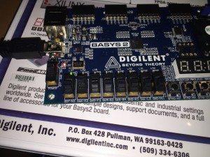
Now I started with a Basys2.
I can count the seconds 🙂 that is the most important thing!
Stay tuned soon I have real clock with hours and minutes.
If you're inventing and pioneering, you have to be willing to be misunderstood for long periods of time
I have made clocks using different hardware.
Now I started with a Basys2.
I can count the seconds 🙂 that is the most important thing!
Stay tuned soon I have real clock with hours and minutes.
 At first the good idea is to draw down signals from the input to the output. Basically it is the truth table:
In the header we can see seven segment display led signals (ca…cg)
Out – decimal number I hope to display and sw3…sw0 input in binary.
-------------------------------------------------
--ca |cb |cc |cd |ce |cf |cg |out|sw3|sw2|sw1|sw0
-------------------------------------------------
-- 1 | 0 | 0 | 1 | 1 | 1 | 1 | 1 | 0 | 0 | 0 | 1
-- 0 | 0 | 1 | 0 | 0 | 1 | 0 | 2 | 0 | 0 | 1 | 0
-- 0 | 0 | 0 | 0 | 1 | 1 | 0 | 3 | 0 | 0 | 1 | 1
-- 1 | 0 | 0 | 1 | 1 | 0 | 0 | 4 | 0 | 1 | 0 | 0
-- 0 | 1 | 0 | 0 | 1 | 0 | 0 | 5 | 0 | 1 | 0 | 1
-- 1 | 1 | 0 | 0 | 0 | 0 | 0 | 6 | 0 | 1 | 1 | 0
-- 0 | 0 | 0 | 1 | 1 | 1 | 1 | 7 | 0 | 1 | 1 | 1
-- 0 | 0 | 0 | 0 | 0 | 0 | 0 | 8 | 1 | 0 | 0 | 0
-- 0 | 0 | 0 | 1 | 1 | 0 | 0 | 9 | 1 | 0 | 0 | 1
-- 0 | 0 | 0 | 0 | 0 | 0 | 1 | 0 | 0 | 0 | 0 | 0

Now we have functional relation between the input and the output so lets implement it in VHDL:
process (sw) BEGIN case sw is when "0001" => segment7 <= "1001111"; -- 1 when "0010" => segment7 <= "0010010"; -- 2 when "0011" => segment7 <= "0000110"; -- 3 when "0100" => segment7 <= "1001100"; -- 4 when "0101" => segment7 <= "0100100"; -- 5 when "0110" => segment7 <= "1100000"; -- 6 when "0111" => segment7 <= "0001111"; -- 7 when "1000" => segment7 <= "0000000"; -- 8 when "1001" => segment7 <= "0001100"; -- 9 when "0000" => segment7 <= "0000001"; -- 0 when others => segment7 <= "1111111"; -- blank end case; END process; Quite easy :) - full code is locating https://github.com/margusja/binary2decimalLed/blob/master/one.vhd But this is not I want. In hardware we can not do thinks like case. So lets move closer to the hardware.This is not optimized solution but much closer to hardware than previous one. Update Got time and optimized logic.
And sentences are much better compared previous ones:
--ca <= (not sw3 AND not sw2 AND not sw1 AND sw0) OR (not sw3 AND sw2 AND not sw1 AND not sw0);
ca <= (not sw0 AND sw2 AND not sw3) OR (sw0 AND not sw1 AND  not sw2 AND not sw3);
cb <= (sw0 AND not sw1 AND sw2 AND not sw3) OR (not sw0 AND sw1 AND sw2 AND not sw3);
cc <= (not sw3 AND not sw2 AND sw1 AND not sw0);
--cd <= (not sw3 AND not sw2 AND not sw1 AND sw0) OR (not sw3 AND sw2 AND not sw1 AND not sw0)
--		OR (not sw3 AND sw2 AND sw1 AND sw0) OR (sw3 AND not sw2 AND not sw1 AND sw0);
cd <= (sw0 AND not sw1 AND not sw2) OR (not sw0 AND not sw1 AND sw2 AND not sw3) OR
		(sw0 AND sw1 AND sw2 AND not sw3);
--ce <= (not sw3 AND not sw2 AND not sw1 AND sw0) OR (not sw3 AND not sw2 AND sw1 AND sw0)
--			OR (not sw3 AND sw2 AND not sw1 AND not sw0) OR (not sw3 AND sw2 AND not sw1 AND sw0)
--			OR (not sw3 AND sw2 AND sw1 AND sw0) OR (sw3 AND not sw2 AND not sw1 AND sw0);
ce <= (sw0 AND not sw3) OR (not sw1 AND sw2 AND not sw3) OR (sw0 AND not sw1 AND not sw2);
--cf <= (not sw3 AND not sw2 AND not sw1 AND sw0) OR (not sw3 AND not sw2 AND sw1 AND not sw0)
--		OR (not sw3 AND not sw2 AND sw1 AND sw0) OR (not sw3 AND sw2 AND sw1 AND sw0);
cf <= (sw1 AND not sw2 AND not sw3) OR (sw0 AND not sw2 AND not sw3) OR (sw0 AND sw1 AND not sw3);
--cg <= (not sw3 AND not sw2 AND not sw1 AND sw0) OR (not sw3 AND sw2 AND sw1 AND sw0)
--		OR (not sw3 AND not sw2 AND not sw1 AND not sw0);
cg <= (not sw1 AND not sw2 AND not sw3) OR (sw0 AND sw1 AND sw2 AND not sw3);
30 bit counter last 8 bits (22 to 29) connected to leds
Tuli tahtmine kella ehitada.
Vanast ajast oli olemas LCD 16X4, RTC ja arduino R3
Ullult olin soetanud LCD expanderi – https://taaralabs.eu/lcd-plug/
RTC annab kella võimaluse. Kui toide välja võtta, siis kenasti tiksub edasi ja hoiab kellaaega õigena.
MCP23008 – annab vabaks hulga arduinio porte, vastasel juhul poleks ilmselt RTC ka kuhugi panna.
Hetkel selline laiali prototüüp, kes teab kas see kuhugi kaugemale jõuabki.
Koodiosa tuleb kõvasti tuunida, hetkel suht häbi selle osa üle.
Näiteks on nädalapäev ühe päeva võrra nihkes.
Esimene versioon tõesti halba koodi – https://github.com/margusja/ArduinoRTC
Osa2
Kuna kogu arduino plaati ühe kella alla matta on minu jaoks liigne luksus, siis otsustasin selle osa eraldi Atmega328P kätte anda. Alguses oli plaan ilma välise kellata, aga hetkel on siis välise 16MH kellaga.
Ühendasin ISP atmega328P’ga:
Allikas: http://upvector.com/atmega/
Minul sai selline asi. Programmaator on mul avrispmkII
Ja oh seda õnne:
margusja@IRack:~/Documents/Arduino/hardware/breadboard/avr$ avrdude -c avrispmkII -v -p ATMEGA328P -P usb
avrdude: Version 5.11.1, compiled on Feb 12 2013 at 01:24:54
Copyright (c) 2000-2005 Brian Dean, http://www.bdmicro.com/
Copyright (c) 2007-2009 Joerg Wunsch
System wide configuration file is “/usr/local/CrossPack-AVR-20130212/etc/avrdude.conf”
User configuration file is “/Users/margusja/.avrduderc”
User configuration file does not exist or is not a regular file, skipping
Using Port : usb
Using Programmer : avrispmkII
avrdude: usbdev_open(): Found AVRISP mkII, serno: 000200133546
AVR Part : ATMEGA328P
Chip Erase delay : 9000 us
PAGEL : PD7
BS2 : PC2
RESET disposition : dedicated
RETRY pulse : SCK
serial program mode : yes
parallel program mode : yes
Timeout : 200
StabDelay : 100
CmdexeDelay : 25
SyncLoops : 32
ByteDelay : 0
PollIndex : 3
PollValue : 0x53
Memory Detail :
Block Poll Page Polled
Memory Type Mode Delay Size Indx Paged Size Size #Pages MinW MaxW ReadBack
———– —- —– —– —- —— —— —- —— —– —– ———
eeprom 65 20 4 0 no 1024 4 0 3600 3600 0xff 0xff
flash 65 6 128 0 yes 32768 128 256 4500 4500 0xff 0xff
lfuse 0 0 0 0 no 1 0 0 4500 4500 0x00 0x00
hfuse 0 0 0 0 no 1 0 0 4500 4500 0x00 0x00
efuse 0 0 0 0 no 1 0 0 4500 4500 0x00 0x00
lock 0 0 0 0 no 1 0 0 4500 4500 0x00 0x00
calibration 0 0 0 0 no 1 0 0 0 0 0x00 0x00
signature 0 0 0 0 no 3 0 0 0 0 0x00 0x00
Programmer Type : STK500V2
Description : Atmel AVR ISP mkII
Programmer Model: AVRISP mkII
Hardware Version: 1
Firmware Version Master : 1.23
Vtarget : 5.1 V
SCK period : 8.00 us
avrdude: AVR device initialized and ready to accept instructions
Reading | ################################################## | 100% 0.01s
avrdude: Device signature = 0x1e950f
avrdude: safemode: lfuse reads as FF
avrdude: safemode: hfuse reads as DE
avrdude: safemode: efuse reads as 5
avrdude: safemode: lfuse reads as FF
avrdude: safemode: hfuse reads as DE
avrdude: safemode: efuse reads as 5
avrdude: safemode: Fuses OK
avrdude done. Thank you.
Part 3
Peale juhtmete ümbertõstmist ja uue kivi programmeerimist on pilt ikka segane, aga arduino sai vahelt minema.
Kuna on plaanis kivil lock bitte ja fuses muuta, siis tundub, et siinkohal on ka õige praegused setingud maha kirjutada
avrdude -c avrispmkII -v -p ATMEGA328P -P usb -U lfuse:r:-:h -U hfuse:r:-:h -U efuse:r:-:h
Reading | ################################################## | 100% 0.00s
avrdude: writing output file “<stdout>”
0xff
avrdude: reading hfuse memory:
Reading | ################################################## | 100% 0.00s
avrdude: writing output file “<stdout>”
0xda
avrdude: reading efuse memory:
Reading | ################################################## | 100% 0.00s
avrdude: writing output file “<stdout>”
0x5
avrdude: safemode: lfuse reads as FF
avrdude: safemode: hfuse reads as DA
avrdude: safemode: efuse reads as 5
avrdude: safemode: Fuses OK
Ja ega ma neid peast ei arvuta – http://www.engbedded.com/fusecalc/
Part 4.5 – Asja lihtsustamiseks võtsin kasutusele sisemise kella (avrdude: safemode: lfuse reads as C2).
Nüüd on prototüüp võimalikult lihtne.
Vol1 – Sisu ehitamine
Internet peab paistma elus, seega peab internet vähemalt vilkuma.
Minu eesmärk oli kasutada nn vanakooli lahendust, kus vilkumisel kasutatakse kondensaatori omadust, mitte programmeerida vilkumist. Kasutasin skeemi, mis on toodud joonisel 1.
Joonis 1. Allikkas: http://cappels.org/dproj/simplest_LED_flasher/Simplest_LED_Flasher_Circuit.html
Ma 2N2222 ei leidnud, aga mul oli kodus 2N2219A, mis toimib samuti.
Kiire prototüüp toimib.
Pildil olev parempoolne kivi ei ole ühendatud.
Varsti tuleb vol2 – internet peab olema ka ilus.
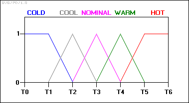
We start by defining the input temperature states using “membership functions”:

With this scheme, the input variable’s state no longer jumps abruptly from one state to the next. Instead, as the temperature changes, it loses value in one membership function while gaining value in the next. In other words, its ranking in the category of cold decreases as it becomes more highly ranked in the warmer category.
At any sampled timeframe, the “truth value” of the brake temperature will almost always be in some degree part of two membership functions: i.e.: ‘0.6 nominal and 0.4 warm’, or ‘0.7 nominal and 0.3 cool’, and so on.
In practice, the controller accepts the inputs and maps them into their membership functions and truth values. These mappings are then fed into the rules. If the rule specifies an AND relationship between the mappings of the two input variables, as the examples above do, the minimum of the two is used as the combined truth value; if an OR is specified, the maximum is used. The appropriate output state is selected and assigned a membership value at the truth level of the premise. The truth values are then defuzzified. For an example, assume the temperature is in the “cool” state, and the pressure is in the “low” and “ok” states. The pressure values ensure that only rules 2 and 3 fire:
https://en.wikipedia.org/wiki/Fuzzy_control_system
Lately I discovered IoT and Clayster for my self.
One good way to learn new things is to resolve some problem using new technology. So I thought to build system detects is somebody is behind in my display. And I’d like to detect it over XMPP.
So for prototyping Raspberry Pi is suitable piece of hardware. Also I used ultrasonic sensors – hc-sr04
Connected with RP using schema
Source: http://www.modmypi.com/blog/hc-sr04-ultrasonic-range-sensor-on-the-raspberry-pi
And I can read readings over XMPP
And finally the most coolest thing – HomeArena by Clayster